



Xhorse Dolphin XP-005 Generation 1 automatic key cutting machine may require maintenance or component replacement after prolonged use. This guide covers common repairs, including battery, mainboard, screen, motor, sensor, wiring, spindle, USB port, and clamp replacement.
Applicable models: Dolphin Generation 1 with serial numbers KM06 and KM12.
1. Battery and Mainboard Replacement
Battery replacement
Refer to diagrams P1–P4 in the maintenance manual.
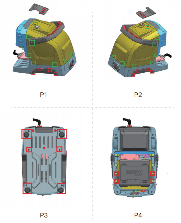
Remove the screws marked in red and take out the battery module.
Install the new battery and reconnect all three wiring ports.
Mainboard replacement
A mainboard replacement may be required if the machine cannot power on, charge, or upgrade, or if it has LED, startup, conductivity, or cutting errors.
Remove the rear cover using the screws marked in green in P1 and P2.
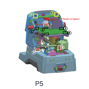
Refer to P5 and remove the screws marked ⑩ and ①–⑤.
Replace the mainboard and reconnect the ports according to the wire harness labels.
2. LED Screen Replacement
Remove the rear cover and the screws marked ⑥ and ⑦ in P5.
Rotate the Z-axis clockwise to its highest position.
Lower the protective cover as shown in P6, rotate the specified column to the left, and remove it.
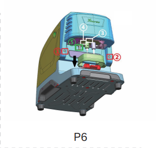
Remove the rubber plugs and screws, then take off the front cover and screen.
Install the replacement screen and reconnect the wiring according to the harness labels.
3. Motor, Belt, and Sensor Replacement
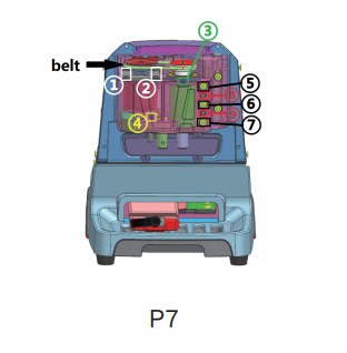
Spindle belt: Remove the front cover and locate the belt in P7. Replace it if it is worn, broken, or slipping.
Spindle motor: Remove the front cover and belt, then remove the screws marked ①–③ in P7 and replace the motor if it makes abnormal noise.
X-axis screw shaft motor: Remove the rear cover, then remove the screws marked ③ and ④ in P8.
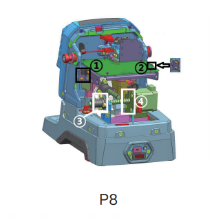
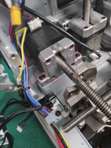
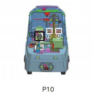
Y-axis and Z-axis screw shaft motors: Remove the mainboard first, then follow the corresponding screw locations in P8 and P10. Check the diagrams carefully before removing the motors.
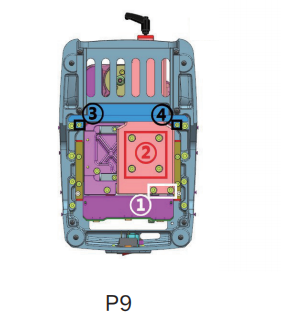
X-axis rail: Remove the battery first, then remove the screws marked ①–④ in P9.
Axis sensors: Remove the rear cover and replace the relevant sensor using P5: X-axis at ⑧, Y-axis at ⑨, and Z-axis at ⑩. Reconnect each port according to the wire harness label.
4. Probe and Cutter Wire Troubleshooting
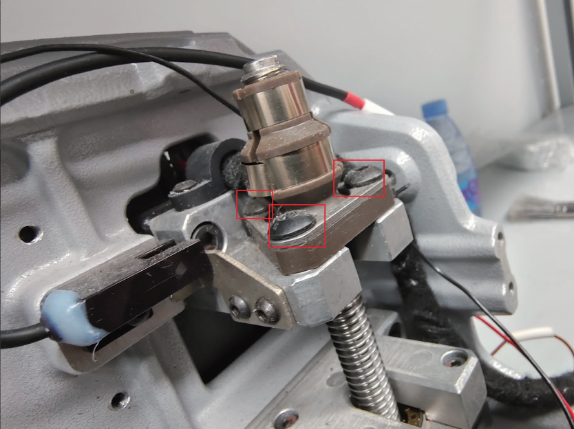
Probe is not conductive: Poor contact or broken wires may be the cause. Remove the front cover and belt, access the probe assembly using P6 and P7, and replace the probe and cutting wires if necessary.
Probe remains conductive: Check for broken probe wires and metal debris near the fixing screws or lamp panel.
Cutter is not conductive: Inspect the wiring for poor contact or a broken circuit. Follow the probe and cutting wire replacement procedure if needed.
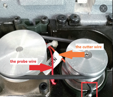
Cutter remains conductive: Check the cutter wire and remove any metal debris carefully. If the problem persists, follow the screw adjustment procedure in P7 and inspect the white insulating paper and the inside of the cutting shaft.
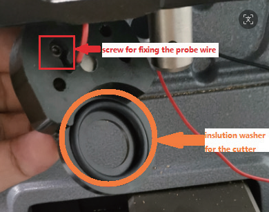
Important: The manual specifically warns not to use an air gun to remove metal debris.
5. Spindle Noise, Shaft, and USB Port Maintenance
Abnormal spindle noise may be caused by metal debris, a worn belt, or excessive clearance in the cutter shaft hole.
Remove the front cover, clean metal debris, replace the worn belt if necessary, and refer to P7 for the specified screw adjustments.
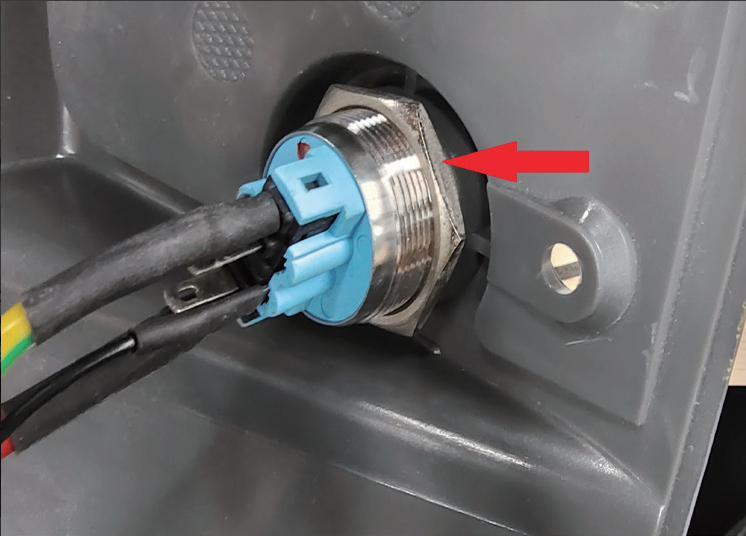
If the probe or cutter shaft threads are damaged and the component cannot be removed normally, follow the relevant probe or cutter disassembly procedure in the manual.
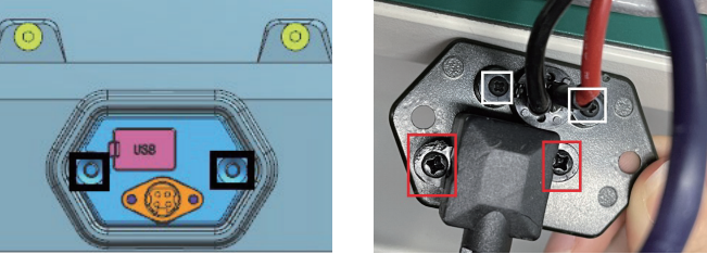
For key switch replacement, remove the rear cover and the retaining nut. For USB port replacement, remove the screws indicated in the corresponding diagram. Reconnect the wiring according to the harness labels.
6. Clamp Replacement
The maintenance manual covers M1, M2, and M5 clamp parts.
M1 clamp: Remove the specified screws and nut, push the knob upward, and replace the clamp surface.
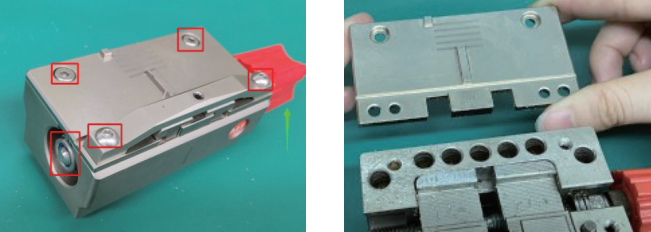
M2 clamp: Rotate the knob outward and replace the required parts. Align the gaps correctly before tightening to prevent the clamp from getting stuck.
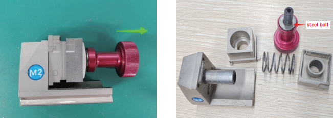
M5 clamp: Remove the specified nut and screws, rotate the knob outward, and replace the relevant components.
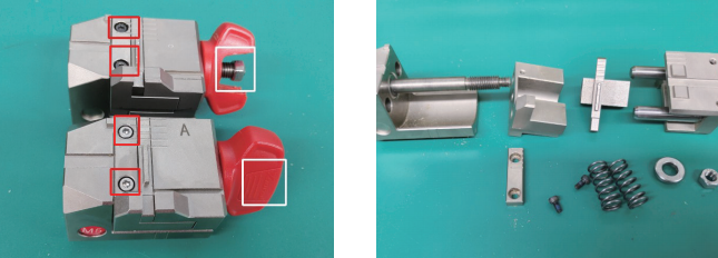
Refer to the original clamp diagrams for component positions and assembly details.
Maintenance Notes
1. Use the original P1–P10 diagrams to identify screws and components.
2. Follow the wire harness labels when reconnecting electrical parts.
3. Inspect the probe and cutter wiring when conductivity problems occur.
4. Do not use an air gun to remove metal debris.
5. Check the belt, spindle assembly, and shaft clearance when abnormal noise occurs.
6. Confirm the correct motor and assembly procedure before replacement, especially when working on the Y-axis and Z-axis mechanisms.
