


Look here: The problem of communication loss Renault Can Clip Alliance VI (926573)
Some of the suggestions from Ineta were confirmed by the results of my experiments.
I took measurements and looked at the oscilloscope.
Has drawn a card of voltages of cards ISO and CAN – it will be necessary for the future.
Analyzed and made sure that the problem is only in the CAN board.
Implemented several improvements in it.
Causes of communication ruptures
- Drawdown voltage 5v c PWM stabilizer.
2. RF interference due to poor high-frequency isolation in the power circuit 5 V.
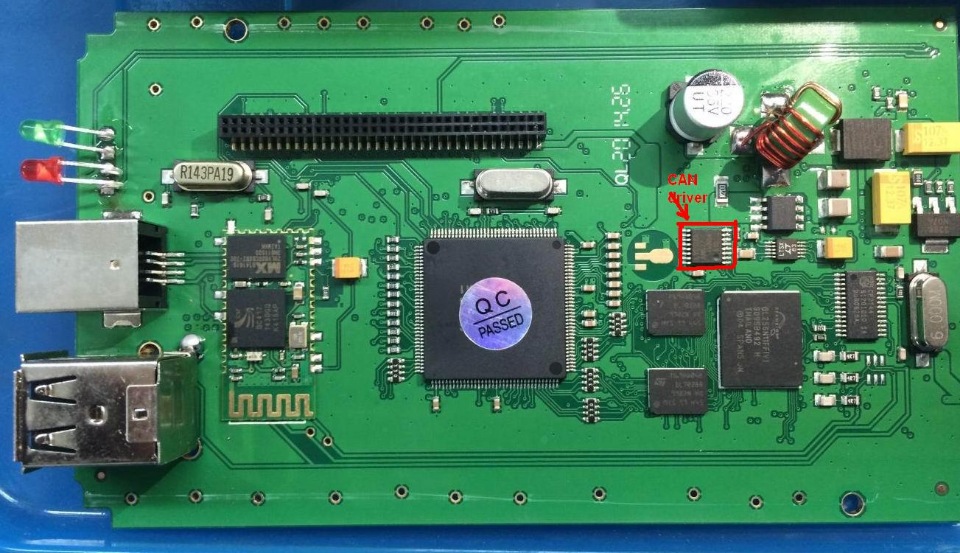
3. Failures in the CAN driver LVC138A (photo 2) – completely eliminated until it was possible
All supply voltages of stabilizers – 12v, 5v, 3v, measured in static and in dynamics – there are no drawdowns.
Intensity of clippings Clip has significantly decreased!
During several hours of work – two short-term connection.
There is a hope to solve the problem to the end.
The simplest modifications have been made, which are available to a non-specialist.
For their implementation, only 20 minutes + a soldering iron and a screwdriver!
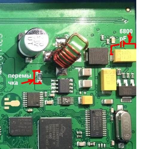
Modifications
(photo 3)
The condenser is necessarily ceramic! For good shunting of high frequency interference
I assume that similar causes of connection failure are also encountered in RTL2002P.
In view of the fact that my work is ideal, I did not conduct experiments on it.
Developments on the problem of connection breaks in the Clip Alliance VI :
- By replacing the boards with an ideally working Clip, it is confirmed that the defect is in the CAN board.
- The consumption current of the Clip is measured in different modes of the Kan Clip program. Measurements on the table – only connect power supply 12 v on the plugOBD 2 clips.
- Theoutput voltages of the sources 12b, 5c, 3c are measured – they correspond and are stable in different modes.
Consumption currents
After connecting = 140Ma
At the request of VIN = 190Ma
When scanning multisets = up to 190Ma
In the monitoring mode = 140Ma
In the sleep mode (one green LED flashes) = 90mA
And, that in the sample probe, that in the probe with the termination of the connection – the currents are the same !!
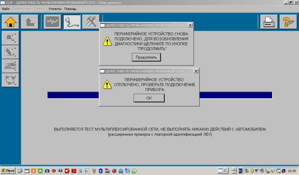
At the time of termination of the connection (ON Clip does not see Alliance VI )
- Current = 140mA – as in the monitoring mode.
- All RF voltages on quartz resonators –are present and without amplitude changes.
- All the voltages of the stabilized sourcesare normal .
In this case, the percentage of CAN of the board issues the command “the connection with the probe Alliance failed”
and, interestingly, the PC does not lose the probe !
This can be seen in – Properties System – Manager devices – 1B-Alliance Vehicule Communication Interface !!!
- To restore communication with the probe, you need to turn the power on and off on it and restart the Clip software. Some kind of chip is hanging! It looks like a processor.
I tried to raise the voltage 5 v to 5.5 v – it did not work.
Queue for 3 v source, want to raise to 3.3 v .
A map of the output voltages from the ISO and CAN boards and the location of the functions of the main chips will be laid out later.
Useful for many when repairing the Clip .
All the best!