


GODIAG GT107 ECU IMMO Kit is a DSG gearbox connection adapter. DSG Gearbox maintenance engineers can clone, diagnose and repair DSG Gearbox ECU and can also read, write and adjust data for DSG Gearbox ECU via PCMFlash, PCMTuner, and Kess V2 etc.
GODIAG GT107 DSG Gearbox Data Read/Write Adapter Support the Connection of:
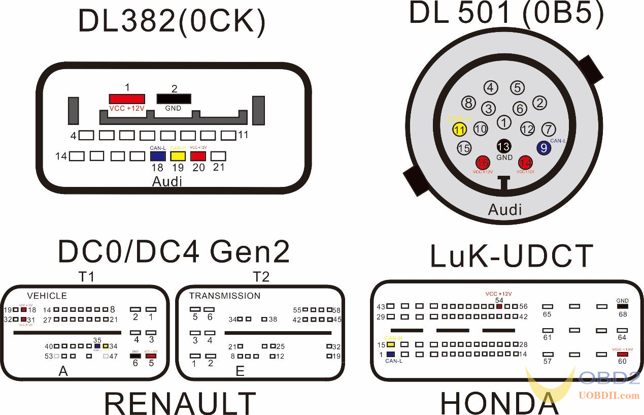
Renault DC0/DC4 Gen2
Honda LUK UDCT
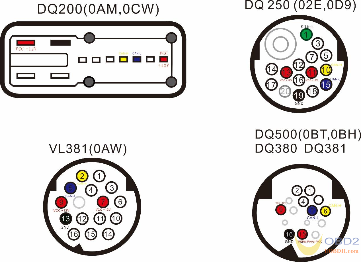
DQ200 (0AM) [WR/CK]
DQ250C (02E) [RD/WR/CK]
DQ250E/F (02E) [WR/CK]
DQ200MQB/G2 (0CW) [WR/CK]
DQ250MQB (0D9) [WR/CK]
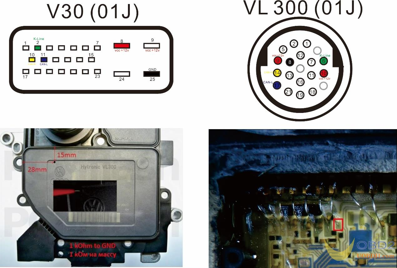
VL300/V30 (01J/0AN) [WR/CK]
VL381 (0AW) [WR/CK]
DL501/G2 (0B5) [WR/CK]
DQ500 (0BH/0BT) [RD/WR/CK] reading when using a direct connection.
DQ200/MQB/G2 Boot (MICRO) [RD/WR/CK]
DQ200/MQB/G2 Boot (EEPROM) [RD/WR]
DQ250E/F/MQB Boot (MICRO) [RD/WR/CK]
DQ250E/F/MQB Boot (EEPROM) [RD/WR]
VL300/V30 BSL (FLASH) [RD/WR/CK]
VL300/V30 BSL (EEPROM) [RD/WR/CK]
VL381 Boot (MICRO) [RD/WR/CK]
VL381 Boot (EEPROM) [RD/WR]
DL501/G2 Boot (MICRO) [RD/WR/CK]
DL501/G2 Boot (EEPROM) [RD/WR]
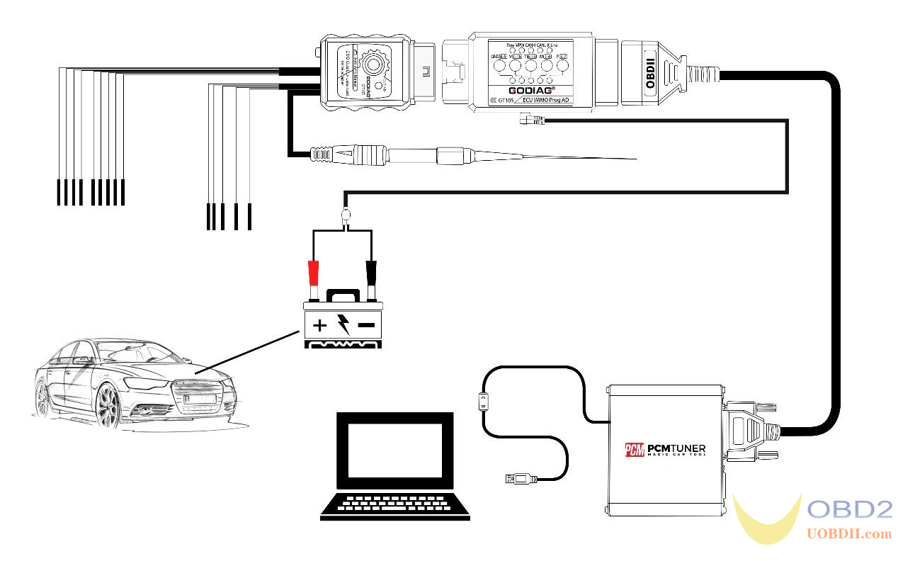
Maintenance workshop connection diagram:

Connection Steps:
- Connect Godiag GT107 tothe gearbox ECU like VAG, DQ250, DQ200, VL381, VL300, DQ500, DL501, for Renault DC0/DC4 Gen2 and Honda LUK UDCT.
- Connect GT105 and connect 12V 2ADCpower supply. (GT105 IMMO function keys must be up.)
- The GODIAG GT107 analogignition switch is in “Auto” mode if it is not pressed, and in “Manual” mode if pressed down(note: please select the corresponding mode in the software to read data)
- Connect PCMFlash,PCMTuner J2534 passthru.
- Perform datareadingand writing operations.
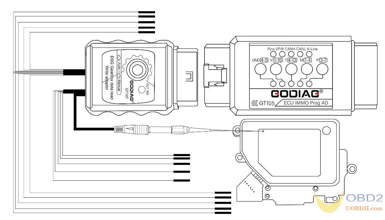
Direct Car Connection Diagram
Steps:
- Connect Godiag GT107 to the gearbox ECU, VAG, DQ250, DQ200, VL381, VL300, DQ500, DL501 for Renault DC0/DC4 Gen2 and Honda LUK UDCT.
- Connect the Godiag GT105 ECU IMMO Prog Adapter and connect the 12V vehicle battery.(The Godiag ECU IMMO Prog AD’s IMMO button must be up.)
- The Godiag GT107 analog ignition switch is in “Auto” mode if it is not pressed, and it is in “Manual”modeif it is pressed down(Note: Please select the corresponding mode in the software for data reading).
- Connect PCMFlash,PCMTuner J2534passthru.
- Perform datareadingand writing operations.
Gearbox ECU interface connection definition:
KESSV2: DQ200, DQ250, DQ500, Connection Diagram

Steps:
- Connect Godiag GT107 to gearbox ECU DQ250, DQ200, DQ500.
- Connect the Godiag ECUIMMOProg AD with the vehicle battery or 12v 3A power supply. (The Godiag ECU IMMO Prog AD’s IMMO button must be up.)
- Connect kessv2 device, andpress down the GT107 switch and it will be in “Manual” ignition mode.
- Pressdown the 120 ohm resistor switch.
- Connectthecomputer and open the software to read and write data.
Work BOOT:use a direct connection to the connector of the control UNIT, the switching power supply is carried out either manually (recommended) or by using the scheme of automatic power control, GODIAG GT107 DSG gearbox data adapter (same PowerBox or converted from KESS). In case of manual control, the entrance to the boot mode may not happen on the first attempt.

Read DQ500: only when connected directly!
NOTE:the power supply must be switched manually, while only the ignition must be switched on or off (pin 15), the second contact must be connected constantly.

Operation in BSL with VL300 / V30: requires drilling a single hole in the minimum diameter cap in order to insert a probe into it. The probe is connected to the GODIAG GT107 DSG Gearbox Data Adapter BOOT 1k ohm GND line(included in the GT107 host). It is mandatory to connect to-line and it is highly recommended to use auto power to quickly “feel” the pin on the board. The photos below show the drilling location and the point on the board where the probe should go.
ECU Disassembly connection pin diagram
