

Xhorse VW MQB48 Function is available now as the latest software of V7.3.1 VVDI2/ V5.2.5 VVDI PROG/ VVDI Key Tool Plus is ready. Here we will share pinouts, free software download and the chip type it supports.
Free Download Software:
V5.2.5 VVDI PROG Software (unzip pass:123456)
Path:
VVDI PROG: 5-DASHBOARD>>VOLKSWAGEN>>MQB-LOCK(D70F35xx)
VVDI2: Key Learn>>MQB platform instrument immobilizer>>Instrument with locked NEC35xx(MQB48, VDO/JCI)
Almost all NEC35XX chips are supported, whether JCI, virtual, or VDO.
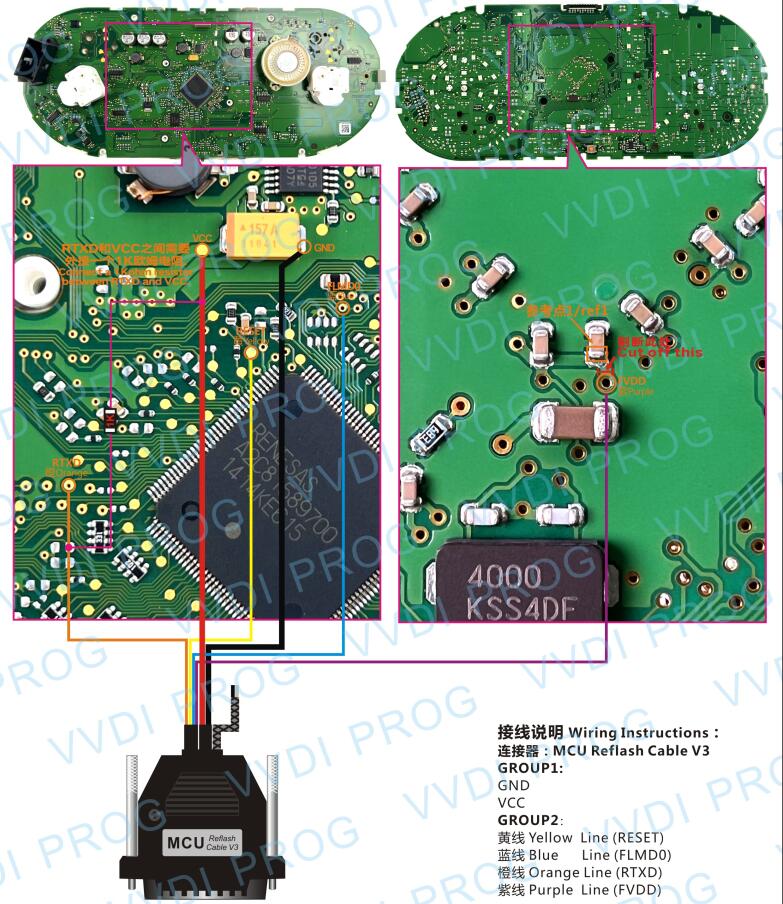
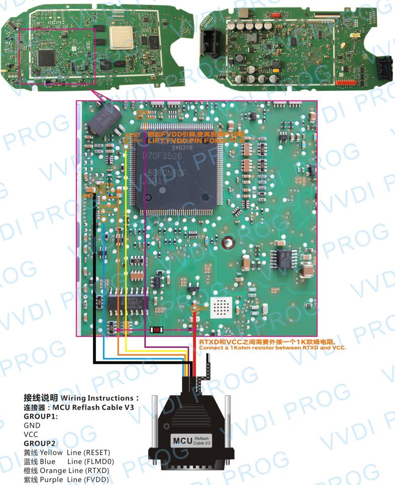
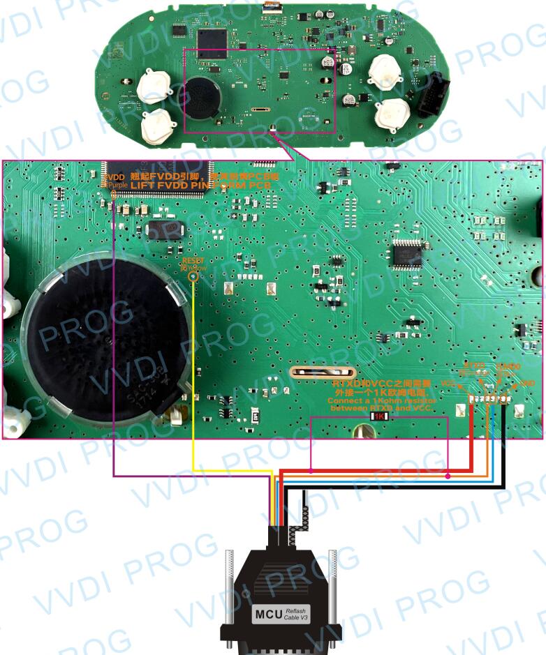
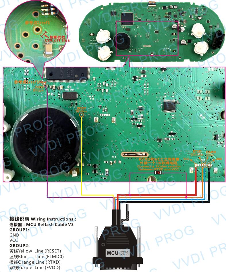
VVDI PROG/ Key Tool Plus supports D70F3525 (2 types), D70F3526 (3 types), D70F3529, and D70F3532.
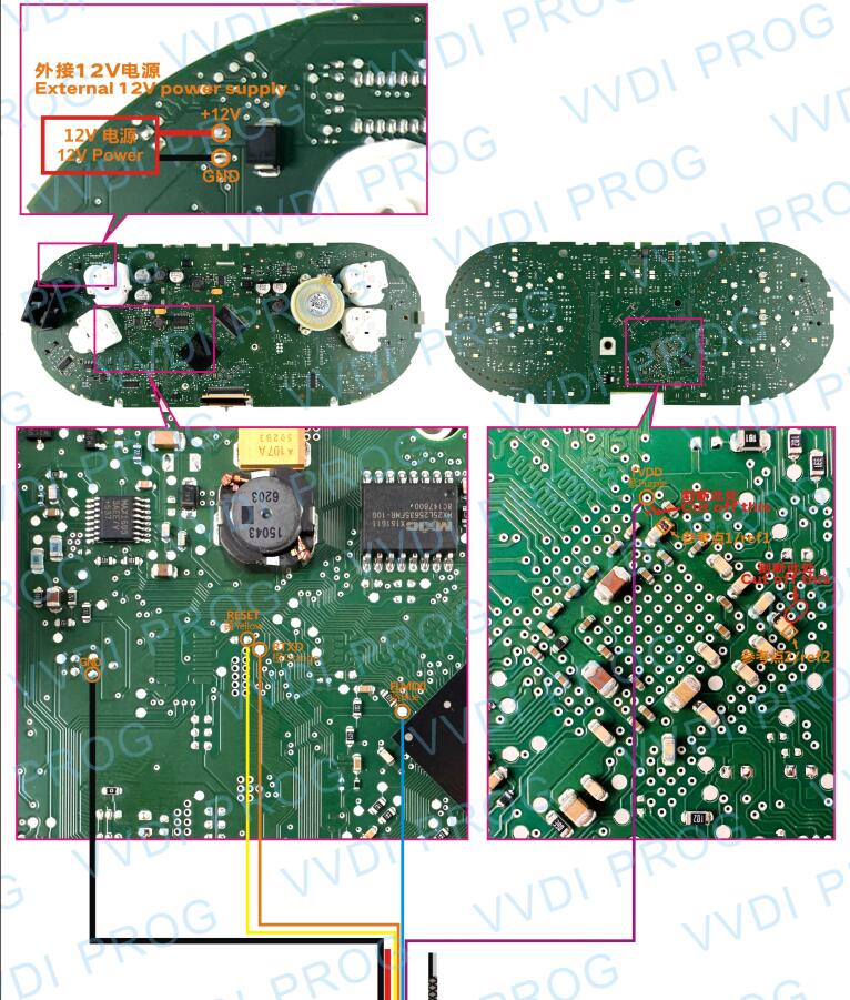
Here are their Pinouts:
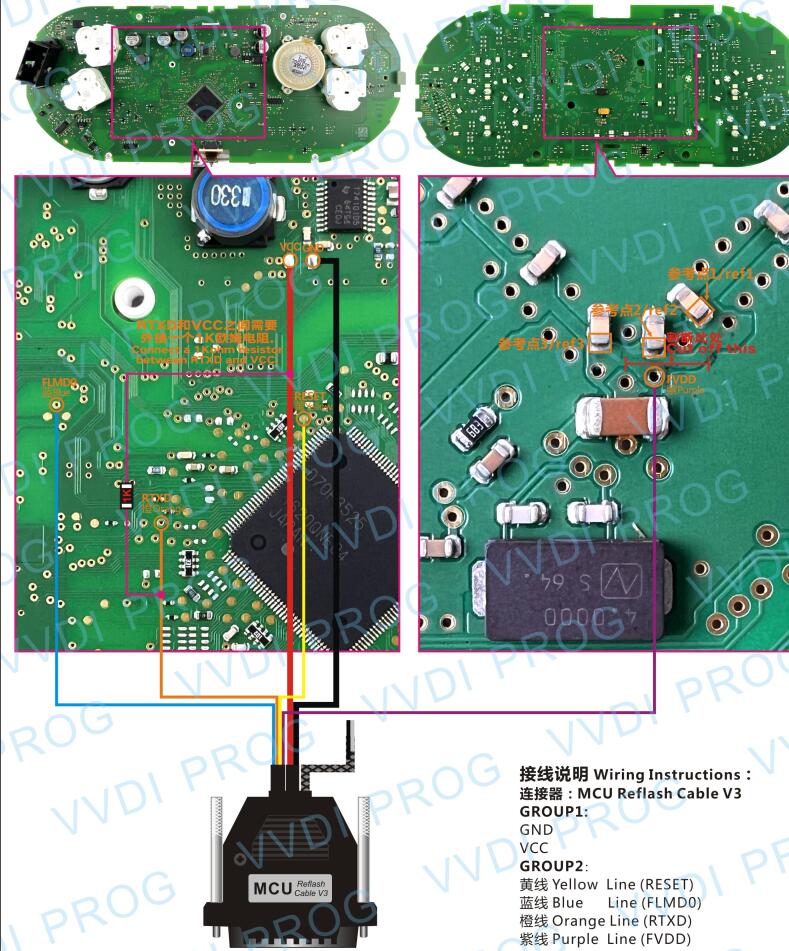
MQB(D70F3525)-A
1)Lift Pin
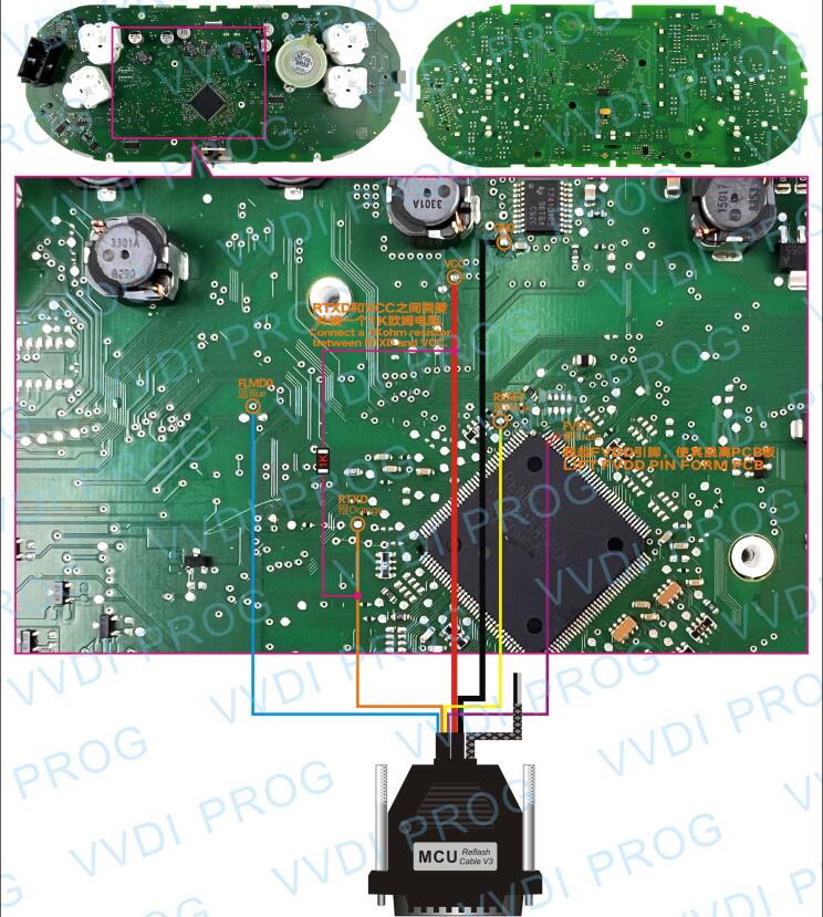
2)Cut Pin
MQB(D70F3525)-B
1)Lift Pin
2)Cut Pin
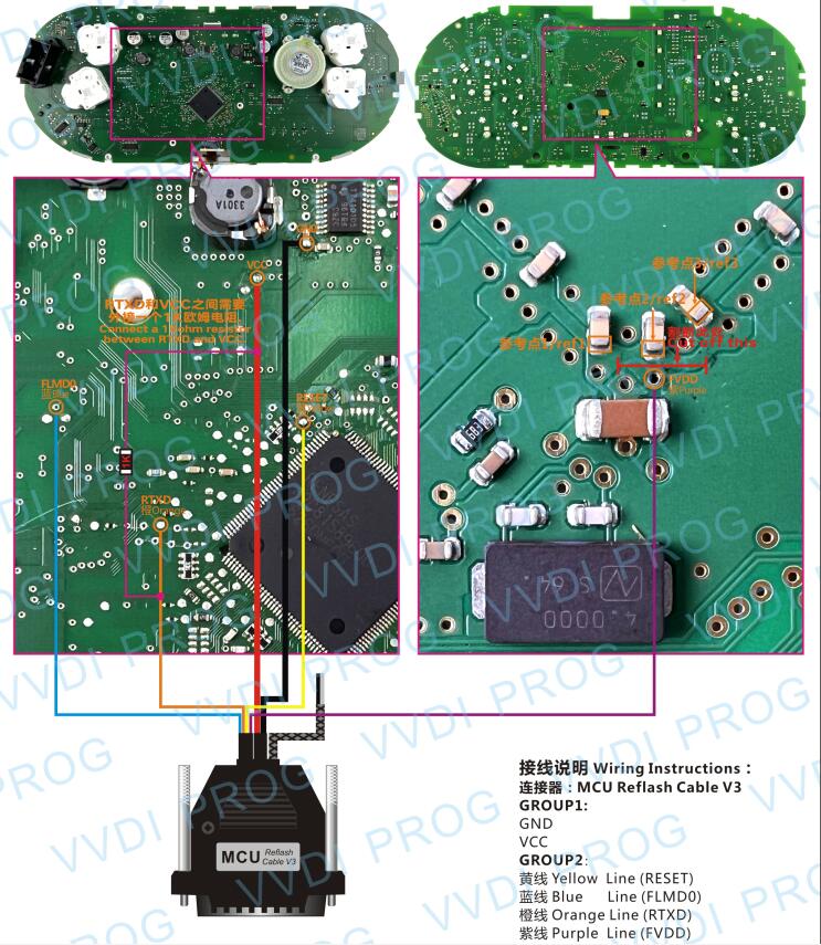
MQB(D70F3526)-A
1)Lift Pin
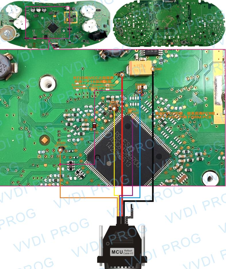
2)Cut Pin
MQB(D70F3526)-B
1)Lift Pin
2)Cut Pin
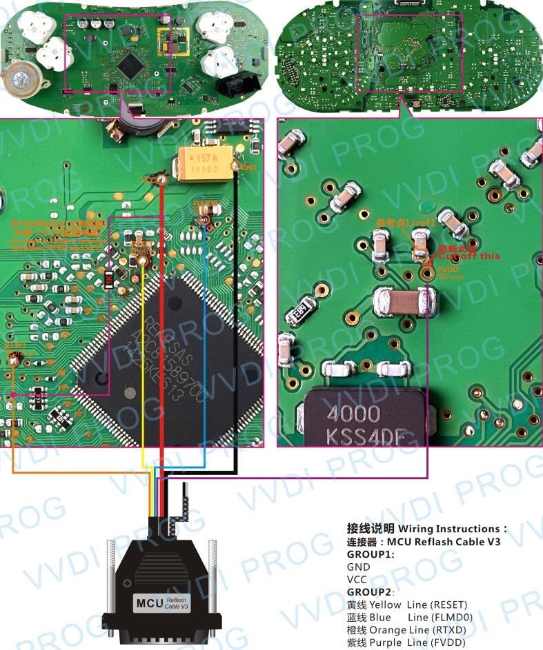
MQB(D70F3526)-C
1)Lift Pin
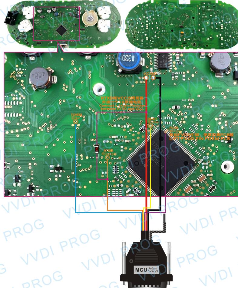
MQB(D70F3529)
1)Lift Pin
2)Cut Pin
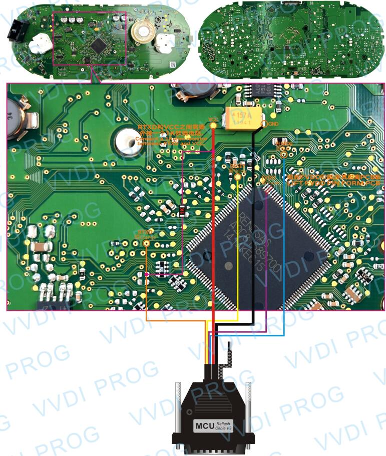
MQB(D70F3532)
1)Cut Pin
There are two ways to read: Lift Pin or Cut Pin. (Cut Pin is safer)
How to Read by Lift Pin?
1.Find the lift PIN ( FVDD ) position according to diagram.
2.Prepare a hot-air gun, set temperature to 355°C/671F, adjust to the lowest speed, focus on the PIN(FVDD) when start operating.
3.After heating the PIN(FVDD), insert the
operating knife under the PIN and lift it slightly up, DON’T lift up too much, just make sure the PIN disconnect with PCB.
4.Wait until the PIN cooling down, soldering a thinwire or a enameled wire from the lift PIN, use
gummed paper to fix this wire on the back of CPU, in case any movement while operating.
5.After Read/Write MCU operation, remove the soldering wire from the lift PIN(FVDD). use the hot-air gun heating the PIN again, then soldering the lift PIN back to PCB(original position)
How to Read by Cut Pin?
1.Find the cutting off the wire position, according to the remarked position and shape for cutting wire as the diagram shown.
2.Follow the instruction and operate slightly while cutting off the wire, Don’t use too much force,otherwise the PCB board will be damaged. .
3.After cut wire successful, check the FVDD point whether disconnect with other reference points as the diagram shown.
4.After Read/Write MCU operation, need to recover the cutting wire position back as before.
Any questions, contact us!
Skype: cardiag.co.uk
WhatsApp: https://wa.me/8615002705698